 |
 |
Bill Brodhead WPB Enterprises Inc
Radon & Vapor Intrusion |
 |
Pressure Drop Above versus Below Fan |
 |
|
WPB Home Page Choosing best Fan to use Reducing System Noise Elevation & Fan Performance All Info pages Piping Pressure Drop Fan Testing method Measuring airflow in pipes Elbows affect under Fan |
 |
|
The amount of system airflow generated by a fan is determined by: 1) The resistance of the sub-slab or sub-membrane 2) The piping size, length and number of elbows 3) The performance of the fan
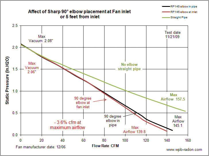
System fans installed outdoors typically have a 90 degree elbow directly below the fan. Some sources claim that having an elbow directly before the inlet side of the fan significantly affects the overall system performance (fan's performance). A test was set up in which an 90 degree sharp four inch elbow was placed directly before the inlet and compared to the performance if the same elbow was place five feet away from the inlet to the fan. Measuring the total static pressure for this setup requires the system resistance to be placed on the outlet side because the resistance between the sharp 90 degree elbow and the fan cannot be measured The location of the resistance being on the outlet side versus the inlet side may also affect the total system performance. A separate test was performed to make this measurement. Measuring the static pressure on the positive outlet side of the fan is not easily done because of the airflow pattern coming out of the fan.
In this first graph the green line represents the fans performance with10 feet of piping and no elbows. The red and black line represent the fans performance when a single 90 degree sharp edged elbow is placed in the piping
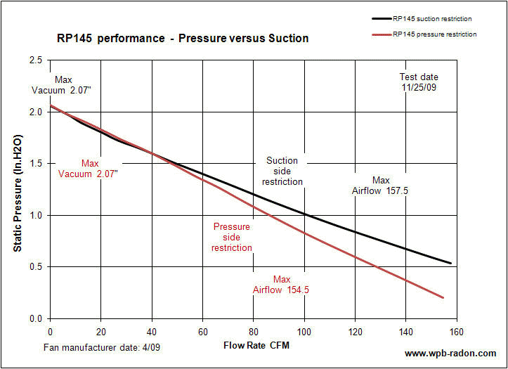
Resistance on the Inlet side was compared to resistance on the outlet side for three different fan types. The first is an RP145 fan. There is no difference up to about 50 CFM. Since the comparison is measuring the fans performance when resistance is changed from inlet to outlet one would assume that there would be greater difference between these two setups as the resistance got greater. Instead the variation happened as the resistance was decreased. This indicates that the difference may be due to the turblence on the outlet side disrupting the static pressure reading.
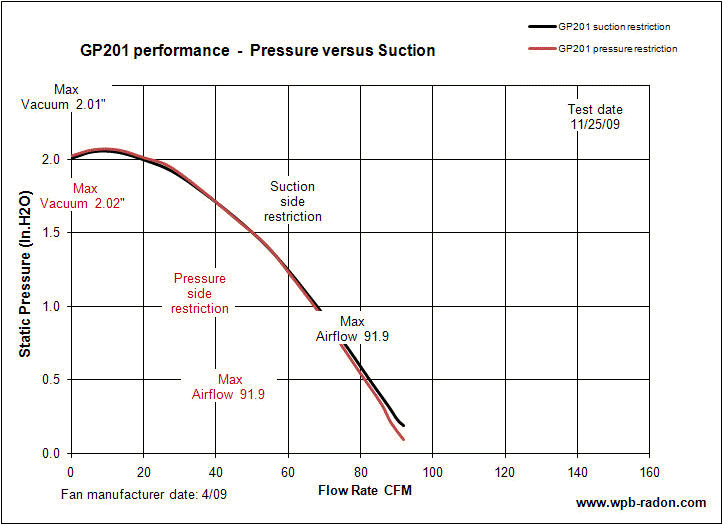
Note that for the GP201 there is very little difference in the performance through most of the fan performance curve. There may be less turbulence on the outlet side of this fan disrupting the static pressure reading.
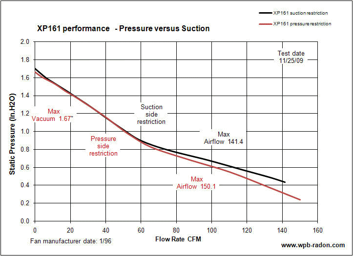
The third fan is an XP161. As with the RP145 there is no difference in performance up to 60 cfm. After 60 cfm there is reduced performance when there is outlet side restriction on the fan. This also could be an error in measurement because of turbulence on the outlet side causing a bias to the static pressure reading. There is also a 9 cfm difference on the maximum airflow which should not be because the maximum airflow is with the least amount of piping resistance.
|
 |
|
Radon Job Photos Fan Performance Lots of Other Info WPB Home |
 |
|
|
|
Radon mitigation call Integra Environmental 610 346-8004 |


