 |
 |
Bill Brodhead WPB Enterprises Inc
Radon & Vapor Intrusion |
 |
|
|
|
Bill Brodhead WPB Enterprises Inc.
Radon & Vapor Intrusion |
|
|
|
|
|
|
Pressure Drop from
|
|
|
Fan Performance Choosing best Fan
Download Fitting & Piping Pressure Drop |
|
The Science of loss of Pressure from Fittings
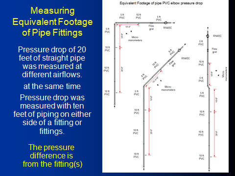
Determining Equivalent Feet of Piping for Different Fittings PVC fittings have different radius turns and shapes, even if two fittings are both 45 or 90 degrees. The resistance is quantified as a pressure drop. To provide a practical unit of resistance the pressure drop induced by the fitting is converted into the equivalent length of piping that would produce the same amount of resistance at the same airflow. As an example, the resistance of one 90 degree elbow is often calculated as having the same resistance as 6 feet of piping. In reality a 90 degree elbow can have significantly less resistance than 6 feet and dramatically more than 6 feet depending on the shape of the elbow and the velocity of the air moving through the piping. In order to better quantify the equivalent length of piping each fitting equals, WPB made direct measurements of fitting and piping pressure drop at varying airflows. Commonly used schedule 40 and schedule 20 (sewer & drain) fittings were installed with 20 feet of piping on one side and 40 feet of piping on the other side. Static pressure probes were installed in the center of a straight run of piping exactly 20 feet apart. At the same time two other probes were used to measure the pressure drop for a fitting with exactly ten feet of piping on either side of the fitting. The difference between these two measurements is the pressure drop of the fitting. This fitting pressure drop difference is divided by the pressure drop of the 20 feet of straight pipe and then multiplied by 20 to obtain the equivalent feet of piping the fitting pressure drop is inducing. The measurement is repeated at nine different velocities and then plotted. The equivalent footage of piping for a particular elbow is included in Figure 5 at a mid velocity of about 75 CFM.
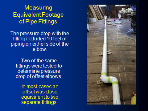
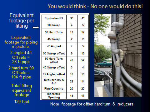
Measuring the pressure drop across two offset fittings. At 75 CFM, a sweep 90 degree elbow is equivalent to 5 feet of straight pipe. A hard turn 90 degree elbow equals 17 feet of straight pipe. Two hard turn 90 degree elbows as displayed in Figure 2 equaled the pressure drop of 52 feet of straight pipe!
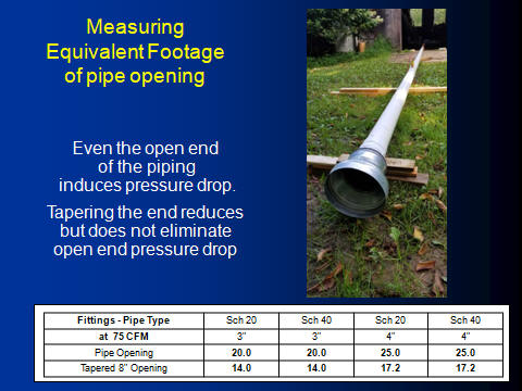
Equivalent Feet of Piping for the inlet of a pipe The table in the Figure 3 quantifies a typical straight into the pipe opening as equivalent to 20 feet of straight pipe for 3" piping and 25 feet of piping for a 4" pipe. This amount of equivalent piping needs to be added to each calculation of total system piping resistance.
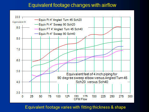
Equivalent feet for different Elbows and Airflow velocity
Equivalent feet of Piping for different fittings Each of those 90 degree hard turn offsets add an extra 42 feet of equivalent piping versus using sweep 90 degree turns. The affect is dramatically less with angled 45 degree fittings versus sweep 45 degree fittings but overall this is an un-necessary resistance when 90 degree sweep elbows acould be used that are 4 to 5 times less resistance.The elbows in Figure 5 radon system have the equivalent footage of 130 feet of pipe.
Determining Equivalent total Footage of Piping
Additional Pressure Drop from Sub-Slab Airflow Resistance Soil depressurization is induced obviously by sucking air out of the soil. Airflow is created by a fan which is working against the resistance to airflow of both the sub-slab material and the piping. In many cases the piping and fittings are the greater resistance. The approximate equivalent footage of different size fittings is given in Figure 5 and Figure 6. This gives the total equivalent straight footage of pipe for a system. If the system has only one suction hole the resistance of all the piping and fittings can be determined by the graphs below. The pressure drop is displayed in the graphs below for 100 equivalent feet of piping. The total equivalent footage (straight pipe footage and all of the equivalent footage of fittings) is divided by 100 and then multiplied by the pressure drop of the piping size and airflow rates of the graph below. Notes: 1) You need to know the speed of the airflow (CFM) to make this calculation. 2) Pressure drop increases with airflow 3) Pressure drop decreases if pipe size increases but airflow stays the same 4) As pipe size increases the equivalent footage of pipe fittings increases 5) Elbows with hard edge turns have more than double the pressure drop of sweep turns. Every PVC fitting has an airflow resistance that is approximately equal to the footage given in the table below. For example each 4" 90 degree sweep elbow adds the equivalent of 6 feet of straight pipe resistance while a 4" 90 degree sharp edged elbow adds 15 feet of equivalent straight pipe resistance. |
|
Figure 6 - Equivalent piping footage for different PVC fittings |
|
Figure 7 - Pressure Drop for 100 feet of 1.5 to 6 piping at different airflows
In the pressure drop chart above the diagonal lines represent different pipe sizes. The horizontal lines represent the airflow though 100 feet of each pipe size. Where the horizontal CFM airflow lines intersect the diagonal pipe size line represents the approximate amount of pressure drop listed on the bottom horizontal line of the chart. An example is 80 CFM airflow through 100 feet of 3" PVC piping would lose about 1 inch of water column of pressure while the same airflow through 4" piping would only lose 0.3 inches of water column. In the chart below the maximum airflow is given for 3" and 4" piping depending upon the length of pipe and the type of fan that is used. Note that an RP140 fan (20 watt) connected to 4" piping will move as much air as an HP220 (120 watt) can move through a 3" pipe. Pipe size typically influences high air flow more than fan size.
Figure 8 - Shows 4in pipe with an RP140 20 watt fan moves as much air as 120 watt HP220 with 3" pipe.
Figure 9 - Airflow difference between HP220 with 4" pipe versus 6in pipe.
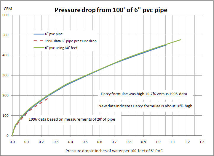
Figure 10 - Pressure Drop Table for 100 feet of 6in piping at different airflows
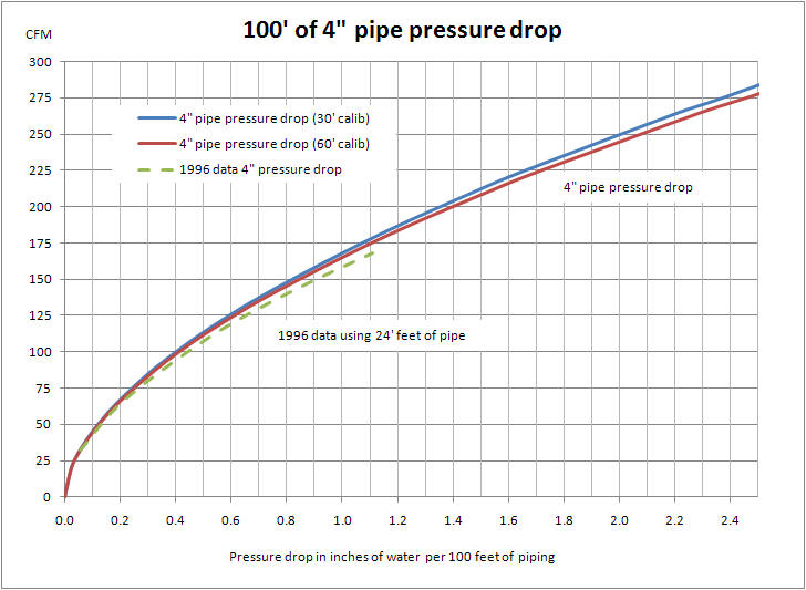
Figure 11 - Pressure Drop Table for 100 feet of 4" piping at different airflows
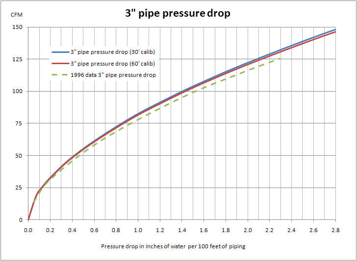
Figure 12 - Pressure Drop Table for 100 feet of 3in piping at different airflows
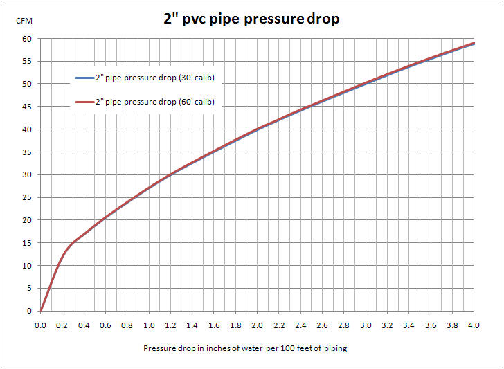
Figure 13 - Pressure Drop Table for 100 feet of 2" piping at different airflows
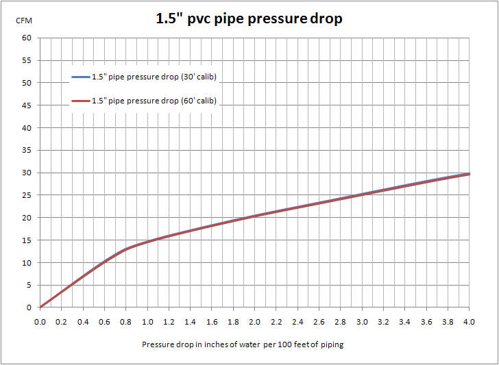
Figure 14 - Pressure Drop Table for 100 feet of 1.5" piping at different airflows |
|
|
Radon Job Photos Fan Performance Download Fitting Piping Pressure Drop |
|
|
The Science of loss of Pressure from Fittings
Determining Equivalent Feet of Piping for Different Fittings PVC fittings have different radius turns and shapes, even if two fittings are both 45 or 90 degrees. The resistance is quantified as a pressure drop. To provide a practical unit of resistance the pressure drop induced by the fitting is converted into the equivalent length of piping that would produce the same amount of resistance at the same airflow. As an example, the resistance of one 90 degree elbow is often calculated as having the same resistance as 6 feet of piping. In reality a 90 degree elbow can have significantly less resistance than 6 feet and dramatically more than 6 feet depending on the shape of the elbow and the velocity of the air moving through the piping. In order to better quantify the equivalent length of piping each fitting equals, WPB made direct measurements of fitting and piping pressure drop at varying airflows. Commonly used schedule 40 and schedule 20 (sewer & drain) fittings were installed with 20 feet of piping on one side and 40 feet of piping on the other side. Static pressure probes were installed in the center of a straight run of piping exactly 20 feet apart. At the same time two other probes were used to measure the pressure drop for a fitting with exactly ten feet of piping on either side of the fitting. The difference between these two measurements is the pressure drop of the fitting. This fitting pressure drop difference is divided by the pressure drop of the 20 feet of straight pipe and then multiplied by 20 to obtain the equivalent feet of piping the fitting pressure drop is inducing. The measurement is repeated at nine different velocities and then plotted. The equivalent footage of piping for a particular elbow is included in Figure 5 at a mid velocity of about 75 CFM.
Measuring the pressure drop across two offset fittings. At 75 CFM, a sweep 90 degree elbow is equivalent to 5 feet of straight pipe. A hard turn 90 degree elbow equals 17 feet of straight pipe. Two hard turn 90 degree elbows as displayed in Figure 2 equaled the pressure drop of 52 feet of straight pipe!
Equivalent Feet of Piping for the inlet of a pipe The table in the Figure 3 quantifies a typical straight into the pipe opening as equivalent to 20 feet of straight pipe for 3" piping and 25 feet of piping for a 4" pipe. This amount of equivalent piping needs to be added to each calculation of total system piping resistance.
Equivalent feet for different Elbows and Airflow velocity
Equivalent feet of Piping for different fittings Each of those 90 degree hard turn offsets add an extra 42 feet of equivalent piping versus using sweep 90 degree turns. The affect is dramatically less with angled 45 degree fittings versus sweep 45 degree fittings but overall this is an un-necessary resistance when 90 degree sweep elbows acould be used that are 4 to 5 times less resistance.The elbows in Figure 5 radon system have the equivalent footage of 130 feet of pipe.
Determining Equivalent total Footage of Piping
Additional Pressure Drop from Sub-Slab Airflow Resistance Soil depressurization is induced obviously by sucking air out of the soil. Airflow is created by a fan which is working against the resistance to airflow of both the sub-slab material and the piping. In many cases the piping and fittings are the greater resistance. The approximate equivalent footage of different size fittings is given in Figure 5 and Figure 6. This gives the total equivalent straight footage of pipe for a system. If the system has only one suction hole the resistance of all the piping and fittings can be determined by the graphs below. The pressure drop is displayed in the graphs below for 100 equivalent feet of piping. The total equivalent footage (straight pipe footage and all of the equivalent footage of fittings) is divided by 100 and then multiplied by the pressure drop of the piping size and airflow rates of the graph below. Notes: 1) You need to know the speed of the airflow (CFM) to make this calculation. 2) Pressure drop increases with airflow 3) Pressure drop decreases if pipe size increases but airflow stays the same 4) As pipe size increases the equivalent footage of pipe fittings increases 5) Elbows with hard edge turns have more than double the pressure drop of sweep turns. Every PVC fitting has an airflow resistance that is approximately equal to the footage given in the table below. For example each 4" 90 degree sweep elbow adds the equivalent of 6 feet of straight pipe resistance while a 4" 90 degree sharp edged elbow adds 15 feet of equivalent straight pipe resistance. |
|
Figure 6 - Equivalent piping footage for different PVC fittings |
|
Figure 7 - Pressure Drop for 100 feet of 1.5 to 6 piping at different airflows
In the pressure drop chart above the diagonal lines represent different pipe sizes. The horizontal lines represent the airflow though 100 feet of each pipe size. Where the horizontal CFM airflow lines intersect the diagonal pipe size line represents the approximate amount of pressure drop listed on the bottom horizontal line of the chart. An example is 80 CFM airflow through 100 feet of 3" PVC piping would lose about 1 inch of water column of pressure while the same airflow through 4" piping would only lose 0.3 inches of water column. In the chart below the maximum airflow is given for 3" and 4" piping depending upon the length of pipe and the type of fan that is used. Note that an RP140 fan (20 watt) connected to 4" piping will move as much air as an HP220 (120 watt) can move through a 3" pipe. Pipe size typically influences high air flow more than fan size.
Figure 8 - Shows 4in pipe with an RP140 20 watt fan moves as much air as 120 watt HP220 with 3" pipe.
Figure 9 - Airflow difference between HP220 with 4" pipe versus 6in pipe.
Figure 10 - Pressure Drop Table for 100 feet of 6in piping at different airflows
Figure 11 - Pressure Drop Table for 100 feet of 4" piping at different airflows
Figure 12 - Pressure Drop Table for 100 feet of 3in piping at different airflows
Figure 13 - Pressure Drop Table for 100 feet of 2" piping at different airflows
Figure 14 - Pressure Drop Table for 100 feet of 1.5" piping at different airflows |
|
|
Radon Job Photos Fan Performance Download Fitting Piping Pressure Drop |
|
|
|
|
|
Radon mitigation call Integra Environmental 610 346-8004 |