How to Design
Correct System Fan and Piping
How do you determine if only
one suction hole is required?
What size piping and fan size
should be chosen?
Pressure Field Extension (PFE) or also called Communication Testing
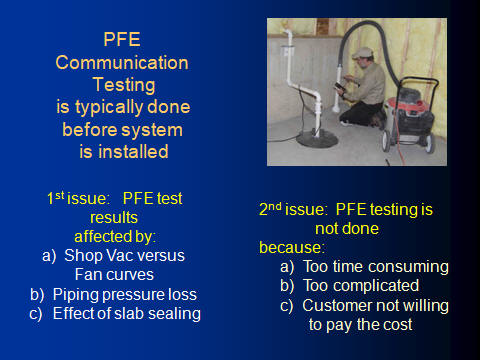
PFE test is used to determine how far a pressure field under a slab can be obtained from a single location. The traditional method is to drill a 1.5" to 2.5" suction hole in the slab at the location that would be optimal for a suction pit and piping. A shop vacuum is often used for this test. A shop vacuum however can produce 50" of water column suction versus typical radon fan maximums of 2 to 4 inches of suction. To compensate for this difference a 1/4" to 3/8" test hole is drilled a few inches away from the suction hole and the vacuum suction is adjusted with a 20 amp speed control or by having an air release valve on the suction pipe riser. At the same time the airflow produced by the vacuum is also measured. See the photo in Slide 1. The vacuum under the slab at the suction hole is adjusted to match a fan curve having a similar airflow at the same vacuum as the test hole. All of this requires measuring the sub-slab vacuum while measuring the airflow and having fan curve charts for common fans. This also does not take into consideration the additional airflow resistance from the piping that will be installed on the system. Slide 1 lists the issues with traditional PFE Testing.
Visit measuring airflow in pipes for information on how to make airflow measurements.
Slide 1
The most important diagnostic tool is a micro-manometer.
It is crucial to have a unit that accurately measures down to 0.1 pascals or 0.004" of water column. A radon mitigator is not a qualified professional unless they have and use a micro-manometer.
This TEC DG8 sells for about $700. An important feature with any
micro-monometer is it's ability to self zero since all of the units drift
from temperature changes. This unit and the EIC CT008 provide blue
tooth connection to your smart phone that allows the unit to monitor
displat pressure at a test hole while you are adjusting vacuum suction at
another location.

Here are some common units that are available as of 2019:
EIC CT008,
Infiltec DM1, Retro-Tec DM2, Infiltec DM4
TEC DG-8

Slide 2
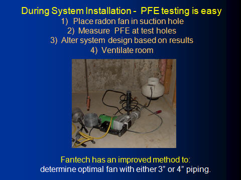
A simple PFE method any Mitigation Company can do.
All that is required for this method is to place a temporary test fan with a rubber boot into a suction hole as soon as it is dug out. Slab sealing should be done prior to this test. Drill a 5/16" test hole at the far corner of the basement or slab. Vacuum the dust created by the drilling. Close windows and exterior doors. Measure and record the sub-slab pressure without the fan running. Turn the fan on and measure the pressure change. Does it reverse to a negative value? If there is no change or only a slight change, remeasure with fan off and then fan on to confirm the results. If no change then additional suction holes are typically needed. If the change is minimal (a few tenths of a pascal or thousands of WC) then do additional digging of the pit, removing 5 to 10 gallons and do more thorough slab sealing. Retest the sub-slab pressure to see if it improved. Limit the run time of the fan because it will quickly raise the radon levels. After the test is finished, open windows and ventilate the space with a fan.
Slide 3
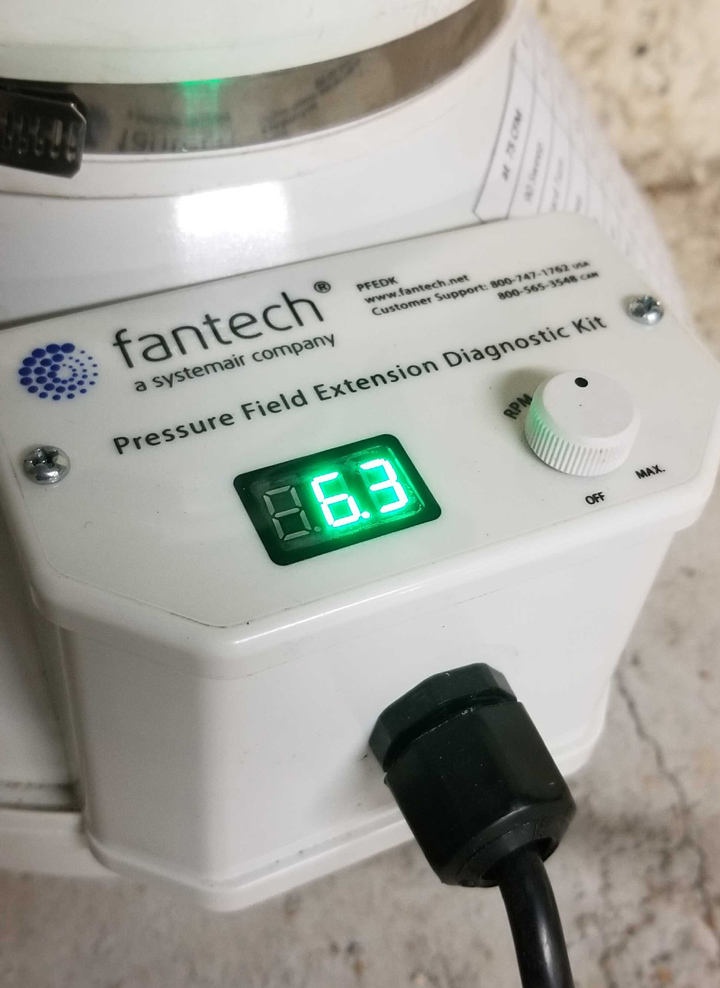
Fantech sells a Pressure Field Extension Diagnostic Kit - PFEDK
The PFE kit uses a modified version of their RN4EC-4 fan. This fan has a display of the DC voltage built into the electrical connection cap as
well as a knob for adjusting the voltage. See slide 7. The
motor voltage can be reduced to the fan wattage of a common low wattage
AC fan (less than 18 watts). The voltage can also be raised to its
maximum of 10 setting, to produce a maximum of 4.5 inches of WC or a
maximum airflow of 300 CFM with ten feet of 4" piping (164 watts at full
airflow). The PFEDK test is performed in a similar manner to the above
simple PFE test. Fantech recommends sealing a short piece of 4"
pipe into the suction hole and then attaching the PFEDK fan to this
pipe. The PFEDK fan is then run at full voltage (10.0). It
is recommended to use dryer duct hose to route the exhaust to the
outside or minimize the run time of the test. Fantech provides separate guidance to compensate for the
resistance of this ducting. The pressure across the fan is
measured using the ports installed in the rubber boots above and below
the fan. The result is entered into the PFEDK app that
requires cell service or wifi connection. The fan voltage is
then adjusted until the far test hole sub-slab negative pressure is
achieved. Fantech recommends a minimum of 0.010" of WC or 2.5
pascals of negative pressure. The PFEDK App is then started and the
recorded pressure across the fan at the 10.0 voltage setting is input at "Static Pressure"
line. The final voltage setting used for optimal sub-slab vacuum is recorded at
the "RPM Ratio" line. The footage of piping that is estimated to be used and number of elbows is entered
into the app. If the PFEDK fan was vented to the outside with dryer duct, this
additional resistance is entered in the "Calibration Factor" input as
determined from the test procedures for calculating this resistance. The App then displays a
chart with the appropriate fan if using 4" piping or using 3" piping.
Visit the Fantech site at FantechPFEDK

Slide 4
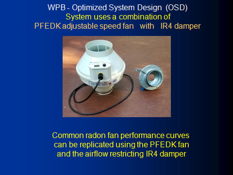
WPB Optimized System Design (OSD)
The PFEDK fan can be adjusted to match the maximum vacuum of all the common radon fans. When the PFEDK fan is adjusted to the maximum vacuum of a
typical radon fan the airflow of the PFEDK is typically much greater. To more closely match the PFEDK to
existing radon fans it was necessary to restrict the airflow of the PFEDK. The IR4 with an iris type damper provided the airflow restriction in a precise
measureable way. See Slide 6 for a picture of the damper. The PFEDK and the IR4 were benched tested by WPB in multiple combinations of
settings to replicate typical radon fan performance curves.
Slide 5
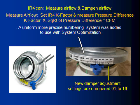
IR4 airflow damper adjustments
The IR4 has a swivel adjustment arm overlaid on K-Factor calibration numbers. If you adjust the damper to one of these K-Factor numbers and multiple that
K number - times the square root of the pressure difference across the damper, using the two grey tubes to make the measurement, it will
provide the CFM of airflow moving through the damper. The OSD (Optimized System Design) does not require you to make this
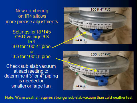
airflow measurement but it is still available to use if CFM airflow is needed. The IR4 K-factor numbers did not provide the necessary precision with the OSD to closely emulate a radon fan. To increase the damper
position setting precision a new number system was installed on the rim of the IR4 damper. The numbering is from 01 to 16. In order to use the OSD a label needs to be made using
Avery-Dennison 18662 clear labels.
The labels and directions can be downloaded at IR4 Label Printout Instructions.
Slide 6
OSD fan is a combination of PFEDK fan and IR4 damper.
The Fantech
Rn4EC-4 can also be used in place of the PFEDK fan. The PFEDK
fan has the significant advantage of a precise voltage display and adjustment
knob built into the electrical connection box on the fan. The Rn4-4 EC
voltage must be varied using a small screw driver to turn the
adjustment dial inside the RN4EC-4 fan electrical box.
Slide 7
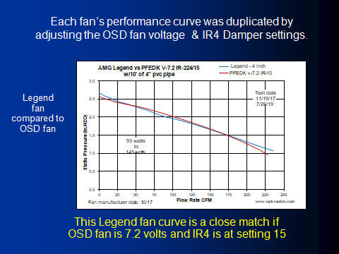
Comparison between OSD fan and typical Radon Fan performance.
The development of OSD fan (PFEDK/IR4) settings to match typical radon fan performance curves starts off with setting the same maximum vacuum.
The airflow is then adjusted with the IR4 damper. This is done using
the WPB fan testing setup that includes 10 feet of 4" PVC piping. In some cases the
performance curve match was very close when plotted. The OSD fan curve in Slide 8 closely matches the Legend
fan curve when the OSD fan is set to 7.2 volts and the IR4 damper is set to number 15.
Slide 8
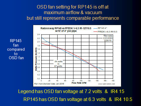
Radon Fans that varied from OSD fan curve
Some of the radon fan curves were more difficult to match to the OSD fan. The top end vacuum and high end airflow needed to be reduced in order for the middle part of the curve to be a closer match. Since
the typical mitigation performance of these fans is more often in the middle
of the curve it was appropriate to use these settings as the closest match for
these fans.
OSD settings were determined for fifteen different
radon fans.
Slide 9
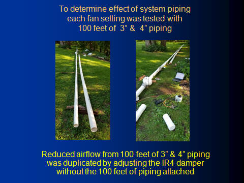
Pressure Drop from 100 feet of Piping
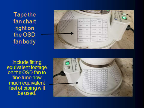
Once the OSD settings for each fan was determined then the next important component of a system design is to include the resistance of the piping and
fittings that the fan must push/pull the air through. Rather than calculate the resistance of piping and fittings, the actual resistance was measured. A
hundred feet of 4" piping was added to the minimum setup of 10 feet of piping. The test was repeated with 100 feet of 3" piping. Each of the
replicated radon fan settings were individually tested with the additional
100 feet of 3" and 4" piping. After the additional 100 feet of 3" or 4" piping was installed, the reduced
airflow was measured and recorded. The OSD fan was then adjusted to the
settings of each of the replicated fans and the original 10 feet of 4"
piping. For each of the replicated fans the IR4 damper was adjusted until the airflow
recorded with the resistance of the 100 feet of piping was replicated using the IR4 damper. Each replicated fan
then had three separate IR4 settings. A setting for a system with only 10 feet of 4" piping, a setting for 110 feet of 4" piping
and a setting for 103 feet of 3" piping. A mitigator can now measure or
guess how much equivalent feet of piping a system will include using
either 3" or 4" piping and adjust the IR4 damper to closely match that
resistance. The OSD voltage setting for that replicated fan would remain the same no matter
how much equivalent feet of piping was used.
Slide 10
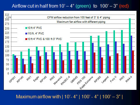
Maximum airflow with 10' and 110' of 4" or 3" Piping
The graph below displays the maximum CFM airflow of each of the replicated fans with three different lengths and sizes of piping. Note
that the maximum airflow with 103 feet of 3" piping is half the airflow of just 10 feet of 4" piping. Notice that the 20 watt radon fans,
RP140 and RN1 move as much air with 4" piping as the 120 watt RP265 and Legend fans can move with 3" pipe.
Pipe size typically determines airflow
capacity more than fan size.
Slide 11
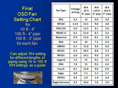
Final OSD chart settings for common radon fans.
The voltage setting for each of the typical radon fans remains the same no matter what type or length of piping is used. What changes is
the IR4 damper setting using the numbering system installed on the IR4 damper. The OSD fan numbering system can be downloaded at OSD Fan settings.
Slide 12
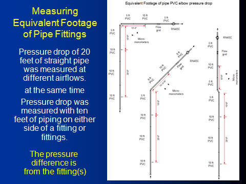
Determining Equivalent Feet of Piping for Different Fittings
The shape and curve radius of a PVC fitting makes a large difference in the resistance it creates to airflow. PVC fittings have different radius turns and shapes, even if two fittings
are both 45 or 90 degrees. The resistance is quantified as a pressure drop. To provide a practical unit of resistance the
pressure drop induced by the fitting is converted into the equivalent length
of piping that would produce the same amount of resistance at the same
airflow. As an example, the resistance of one 90 degree elbow is often
calculated as having the same resistance as 6 feet of piping. In
reality a 90 degree elbow can have significantly less resistance than 6 feet
and dramatically more than 6 feet depending on the shape of the elbow and
the velocity of the air moving through the piping. In order to better
quantify the equivalent length of piping each fitting equals, WPB made direct measurements of fitting
and piping pressure drop at varying airflows. Commonly used
schedule 40 and schedule 20 (sewer & drain) fittings were installed with 20 feet of piping on one side and 40 feet of piping on the other side.
Static pressure probes were installed in the center of a straight run of piping
exactly 20 feet apart. At the same time two other probes were used to measure the pressure drop for a fitting with exactly ten
feet of piping on either side of the fitting. The difference between
these two measurements is the pressure drop of the fitting. This
fitting pressure drop difference is divided by the pressure drop of the 20 feet of straight pipe and then
multiplied by 20 to obtain the equivalent feet of piping the fitting
pressure drop is inducing. The measurement is repeated at nine
different velocities and then plotted. The equivalent footage of
piping for a particular elbow is included in the OSD fan sizing chart at a
mid velocity of about 75 CFM.
Slide 13 illustrates the setup.
Slide 13
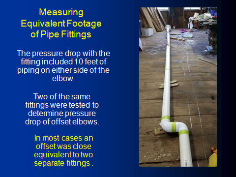
Measuring the pressure drop across two offset fittings.
Radon mitigation installers often need to offset pipe to line it up with the
fan or move around obstacles. Offset arrangements were tested
in the same manner as single fittings. In most cases the offset
pressure drop closely matched the single pressure drop result times the number of
fittings used but in other cases the affect was significantly greater than
the doubling of the single fitting value. This was especially true
with offset hard turn 90 degree elbows. At 75 CFM a sweep 90
degree elbow is equivalent to 5 feet of straight pipe. A hard turn 90
degree elbow equals 17 feet of straight pipe. Two hard turn 90 degree
elbows as displayed in Slide 14 equaled the pressure drop of 52 feet of
straight pipe!
Slide 14
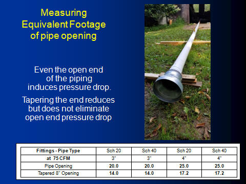
Equivalent Feet of Piping for the inlet of a pipe
Some of the air entering a PVC pipe needs to make a 90 degree turn to enter
the pipe. If the opening to the pipe was tapered, the airflow into
the pipe would be more laminar and have less resistance. See the
tapered setup in Slide 15. The table in the slide 15 quantifies a typical straight into the pipe opening as
equivalent to 20 feet of straight pipe for 3" piping and 25 feet of piping
for a 4" pipe. This amount of equivalent piping needs to be added to
each OSD calculation of total system piping resistance.
Slide 15
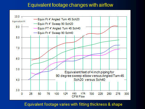
Equivalent feet for different Elbows and Airflow velocity
As air flow velocity in a pipe increases the equivalent pipe length for a
pipe fitting also increases. In the fitting chart that displays the
equivalent footage of piping for each fitting, 75 CFM of airflow was used as
typical system airflow. If typical system airflow is between 25 and
150 CFM the equivalent footage for a 4" sweep 90 degree sch 40 fitting would
vary from about 4 feet of piping to about 6 feet of piping.
Slide 16
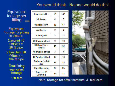
Equivalent feet of Piping for different fittings
The equivalent length of pipe for these different fittings was based on airflow of
75 CFM and rounded to the closest whole number. Note the
difference between a sweep 90 degree fitting and a 90 degree hard
turn fitting. This is especially pronounced difference when you use
two hard turn 90 degree fittings to make an offset as show in the picture in
slide 17. Each of those 90 degree hard turn offsets add an extra 42 feet of
equivalent piping versus using sweep 90 degree turns. The affect
is less with angled 45 degree fittings versus sweep 45 degree fittings
but still an un-necessary resistance based on fitting choice.
TThe OSD
provides a basic equivalent footage of 110 feet of pipe. At the job
site add up the estimated footage of straight pipe. Count the
number of 90 degree and 45 degree elbow and offsets that will be used.
Multiple the quantity of each fitting by the footage equivalent in the table
in Slide 17. Include the pipe opening equivalent footage. Use
the total of piping length and equivalent footage of fittings and opening to
compare to the equivalent footage of the fan chart. Use an approximate
adjustment to the IR4 damper setting based on the actual equivalent footage
of the system being installed.
Slide 17
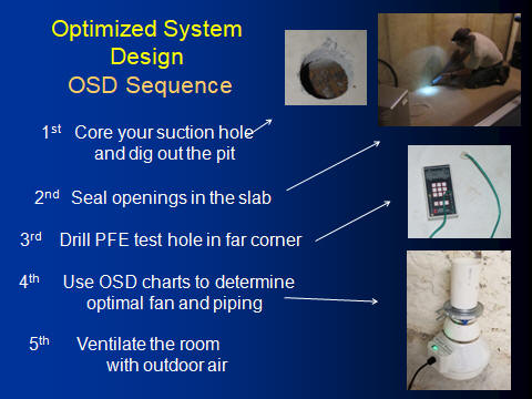
OOSD Sequence
The suction hole needs to be cut through the slab first and the suction
pit dug out. In order to get a valid result, openings through the slab
such as the perimeter joint or open pits need sealing before doing the OSD test.
Sealing even small cracks around the perimeter can increase the sub-slab
vacuum by 10 fold, so slab sealing is important. At
least one small 5/16" test hole is drilled at the far corner of
the slab from the suction pit. A micro-manometer capable of measuring
accurately down to 0.001" of water column or 0.1 pascals is used to measure
the sub-slab pressure difference across the slab.
The windows and exterior doors need to be closed during this test. The OSD fan is placed
into the suction hole using the soft rubber boot under the fan to provide
a reasonable seal. The sub-slab pressure is always measured with the OSD fan
off then with the fan on - to see not only the final sub-slab pressure but to note the
amount of pressure change that happens. Sometimes there is strong positive pressure under the slab (2 to 3 pascals) and the positive pressure is
reduced but not reversed.
Always repeat the on/off test if there is only a slight pressure change. Start with a fan setting for
a fan you have at the job site. Measure the far test hole with the
IR4 set to 110 feet of 4" piping or 103 feet of 3" piping or an approximate
adjustment to these settings based on the determined actual footage of the
system to be installed. The necessary negative pressure under
the slab is described in slide 21.
If the sub-slab vacuum at the test hole is more than required, try changing
the IR4 setting to 3" piping or change both settings to another radon fan that uses less wattage.
If the system is not able to induce any pressure change at the far test hole
than additional suction pits are likely needed rather than a larger fan.
If there is some pressure change but not an adequate amount than do more slab sealing or enlarging the suction pit
to provide additional negative pressure under the slab. See Slide 23.
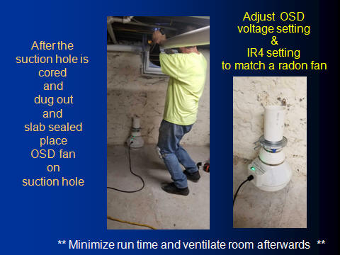
Always minimize the running time of the test fan and ventilate after doing the test with a fan venting outside air.
Slide 18
Print the Fan setting charts & attach to Fan Body
Download the OSD Fan settings. Install the fitting equivalent footage chart on the fan
Slide 19
Example of settings for RP145 fan
The RP145 IR4 damper setting would be 8.0 for 110 equivalent feet of 4" piping or
an IR4 setting of 3.5 for 103 equivalent feet of 3" piping.
Slide 20
Minimum sub-slab test hole Negative Pressure
The goal of radon mitigation is to prevent radon entry by reversing the normal airflow out of the slab. Elevated indoor radon
levels are primarily caused by soil gas movement because the building is
negative in pressure at the slab level in comparison to the soil. This
pressure gradient in residential homes is most likely caused by what is
termed stack effect.
Stack effect is simply the rising of warmer air inside a house compared with the cooler temperatures outside. The
loss of house air predominates at the ceiling of the top floor because the
air is warmest (lightest) there. The greater the temperature differences between
inside and outside, the greater the upward pressure and air loss. This
creates the strongest opposite or house negative pressure in the lowest
level floor. Modern homes with air tight exteriors but openings into
the attic induce strong negative pressures at the lowest level slab.
As the outdoor temperature gets colder the active soil depressurization
system has to be stronger to maintain a sub-slab negative pressure.
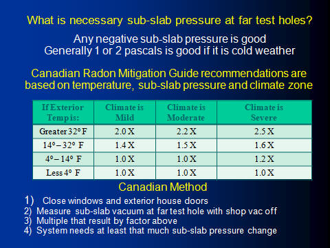
To compensate for winter stack effect the Canadian Radon Mitigation Design manual for professional radon
mitigators includes this table of additional required sub-slab negative
pressure depending upon the outdoor temperature at the time of the test.
The Canadian Radon Mitigation Guidance document recommends measuring the
pressure under the slab at several locations with the test fan or vacuum off
and windows and exterior doors closed. If there is any air handling
equipment located on the lowest level such as a hot air furnace it should be
running during this test with door to the upstairs closed. The bare
minimum pressure change needed for mitigation is the amount that will change
all the far test holes from a positive pressure under the slab to negative
pressure with a stack effect compensation based on the current outdoor temperature. Basically if the
temperature outside is greater than 32 degrees( O centigrade) multiple the
minimum necessary pressure change by 2 to 2.5 depending on the climate zone
of the test. This is a minimum pressure change that needs to be
obtained.
In warm weather if sub-slab pressure is less than +1.0 pascals round up to +1.0 pascal (.004").
Slide 21
Performing the OSD design during system installation
To coordinate the OSD with a system installation sequence it is
necessary to core the slab and dig out the suction pit first and drill the far
test holes through the slab. Any significant slab openings need to be
sealed especially if they are near to the suction pit. If there are
two workmen on site, one could be coring the slab while the other is sealing the
slab.
The routing of four inch pipe through the building to the fan
location could be done while the suction pit is dug out. The windows and exterior doors need to be closed during the
test. The OSD test only requires the OSD fan to be placed on the
suction pit using the rubber boot without the metal clamp or other materials
to create a reasonable seal.
The far test hole is checked for sub-slab pressure with fan off and then with the OSD fan on
and set to an available fan. The far test hole can be
measured with the IR4 damper set for 4" piping and then switched to 3" piping. If
sub-slab vacuum goal is easily achieved than the OSD fan can be re-set for a
lower wattage fan. If there is inadequate but some pressure change
than the suction pit can be enlarged and additional slab sealing done before
repeating the test.
If there is no pressure change than a second suction hole needs to be
installed and the OSD test repeated at that new suction pit location.
If the amount of airflow needs to be determined than the IR4 K-Factor
numbers can be used with the previous instructions given in Slide 6 to determine the
airflow expected with the amount of equivalent piping the system is expected
to have.
Slide 22
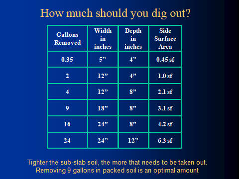
Optimal suction Pit Size
The more the soil is compacted, the smaller the void space between the soil
particles. It requires a much larger surface area to get the same
amount of free space as compared to gravel under a slab. It is
important to excavate a large pit when the sub-slab is compacted soil.
The following table illustrates the increase in surface area as you enlarge
the suction pit size. Optimal size for compacted sub-slab material is
two spackle buckets or about 8 to 9 gallons of dirt.
Slide 23
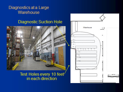
Large Building Diagnostics
Commercial buildings and large buildings in general often require
specialized commercial fans. The OSD is not specifically meant for
these special cases. There are however some lessons that can be
learned from large buildings. In this large warehouse, test holes were
drilled every ten feet out to a maximum of 70 feet. The pressure in
each test hole was measured with the diagnostic fan off and then with fan on
at two different airflows. This test was done to determine actual
sub-slab airflow resistance as well as pressure field extension.
Slide 24
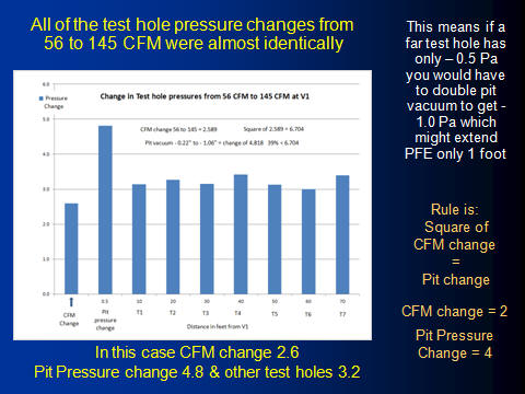
Linear relationship of test hole pressure change
The graph in Slide 25 depicts the difference of the
pressures in each of the test holes that were every ten feet out to 70 feet
from the suction pit. The airflow at the suction pit was 56 CFM at low
speed and 145 CFM at high speed.
Note that the vacuum change in test hole T1 through T7 changed almost identical amounts of a factor of about
3.2 between the two airflows. This shows the linear pressure change
that happens at different sub-slab test holes.
In many cases if the
pressure field does not extend far enough there is often a rush by the
mitigator to just enlarge the fan as the next step. This often does not significantly enlarge the pressure field.
A residential system example is one with a fan that generates a maximum of
2.0 inches of vacuum is replaced with a fan that can generates 4 inches of
maximum vacuum.
What is not considered is that with the higher suction pit
pressure there is also an increased airflow which then has the higher vacuum fan operating at a lower
pressure so that the pit vacuum is not doubled. Even if the vacuum in the test holes
was doubled, the farthest test hole was likely only a few thousands of an inch (tenths of a
pascal) sub-slab vacuum. Doubling this weak pressure will likely only extend the
pressure field a few additional feet at best.
A much larger pressure field area
increase is created by installing an additional suction
pit rather than using a larger fan.
Slide 25
|